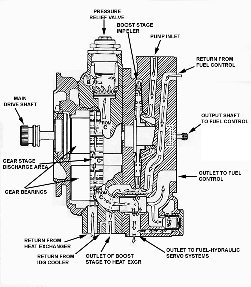
Cutaway drawing of the Engine Driven Fuel Pump ARGO-TECH 708600 SERIES where you can see the high pressure gear stage on the left half, and the low pressure centrifugal stage on the right side.
The Engine Driven Fuel Pump is part of the Airplane fuel system, one of the most important elements of the fuel system, like to any other internal combustion engine equipped vehicle.
There are two types of engine driven fuel pumps used in aircraft jet engines, the Gear type Constant Displacement fuel pumps,and the Piston type Variable Displacement fuel pumps. The operation of the piston type fuel pump is the same with the piston type hydraulic pump described in another page of this web site.
Both pump types are positive displacement, which means that for every pump rotation a certain amount of fuel will come out of the pump exit.
In an overview of the airplane fuel system, the engine driven fuel pump is located downstream of the electrically operated centrifugal type fuel boost pump, located in the fuel tank providing positive fuel pressure to the engine driven fuel pump, and upstream of the pump is the fuel metering unit, the fuel flow meter, and the fuel nozzles.
We will describe here the Gear type Constant Displacement engine driven fuel pump, which means that for every revolution of the pump the same amount of fuel is coming out of the exit at all times, the opposite of the Variable Displacement type where the output volume can be regulated according to the demands of the system.
The gear type fuel pump is used in all the civil jet engines fuel system and in particular this one ARGO-TECH 708600 SERIES we describe here is used on CFM-56 engines installed on Boeing 737 and Airbus 320 airplanes.
The pump is installed on the engine accessory gear box on the aft side of it and at about 20:00 time locking forward, where it is attached with a QUAD ring (Quick attach Detach), which allows easy removal and installation of the unit.
The fuel metering unit is attached on the fuel pump and both units comprise the most important assembly of the jet engine fuel system.
The fuel metering unit and the fuel pump are hydraulically (fuel flow) and mechanically (by a shaft) coupled. Mechanical connection is used from the fuel metering unit to control and monitor (feed back) of the engine speed according to the demands of the operator.
Looking the schematic cutaway of the engine driven fuel pump on thefigure to the left we observe that the pump is made of two parts, the high
pressure stage on the left half, materialized of two gears coupled together and the low pressure stage to the right half, materialized of a centrifugal type (boost) pump.
Mechanical energy from the engine accessory gear box rotates the pump with a ratio 1/1.3 (pump/Engine shaft rpm) through the main drive shaft directly to the upper gear of the high pressure gear stage and the lower gear is driven too as coupled together. The rotary motion then passes from the upper gear of the gear stage directly to the low pressure stage rotor through a internal shaft, so the rotation ratio of the high and low pressure stages are 1/1.The way the two gears of the high pressure stage are coupled together is clearly visible on the cutaway schematic shown from a different angle on the figure to the right.
During operation the pump receives fuel to the pump inlet, as it is shown on the upper figure, from the electrical fuel boost pump located at the fueltanks at a pressure of 40 psi (pounds per square inch).
The low pressure centrifugal stage (boost stage) increases the pressure of the fuel to a value of 170-180 psi (pounds per square inch) at the maximum nominal operating speed (6250 rpm). This initial pressure increase prevents the phenomenon of ”cavitation” to occur at the high pressure stage of the pump at certain conditions.
Next to the low pressure stage the fuel is directed to the fuel-oil cooler where the fuel receives heat from the engine oil to prevent ice crystals to reach next stages of fuel system, and the engine oil is cooled to a lower temperature to improve it’s lubrication characteristics and return cooler to the engine bearings and absorb some heat of them.
After the fuel oil cooler the fuel is entering the low pressure fuel filter. The body of the low pressure filter is integrated on the pump case.

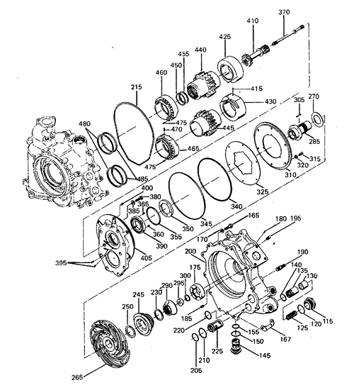
Exploded view of the engine driven fuel pump ARGO-TECH 708600 SERIES showing all the parts it consists off, the body, the high pressure stage gears (440, 445), the low pressure centrifugal type rotor (265), the inter stage plate (395).
Reference: Civil Airplanes maintenance manuals, Airbus, Boeing.
The Engine Driven Fuel Pump is part of the Airplane fuel system, one of the most important elements of the fuel system, like to any other internal combustion engine equipped vehicle.
There are two types of engine driven fuel pumps used in aircraft jet engines, the Gear type Constant Displacement fuel pumps,and the Piston type Variable Displacement fuel pumps. The operation of the piston type fuel pump is the same with the piston type hydraulic pump described in another page of this web site.
Both pump types are positive displacement, which means that for every pump rotation a certain amount of fuel will come out of the pump exit.
In an overview of the airplane fuel system, the engine driven fuel pump is located downstream of the electrically operated centrifugal type fuel boost pump, located in the fuel tank providing positive fuel pressure to the engine driven fuel pump, and upstream of the pump is the fuel metering unit, the fuel flow meter, and the fuel nozzles.
We will describe here the Gear type Constant Displacement engine driven fuel pump, which means that for every revolution of the pump the same amount of fuel is coming out of the exit at all times, the opposite of the Variable Displacement type where the output volume can be regulated according to the demands of the system.
The gear type fuel pump is used in all the civil jet engines fuel system and in particular this one ARGO-TECH 708600 SERIES we describe here is used on CFM-56 engines installed on Boeing 737 and Airbus 320 airplanes.
The pump is installed on the engine accessory gear box on the aft side of it and at about 20:00 time locking forward, where it is attached with a QUAD ring (Quick attach Detach), which allows easy removal and installation of the unit.
The fuel metering unit is attached on the fuel pump and both units comprise the most important assembly of the jet engine fuel system.
The fuel metering unit and the fuel pump are hydraulically (fuel flow) and mechanically (by a shaft) coupled. Mechanical connection is used from the fuel metering unit to control and monitor (feed back) of the engine speed according to the demands of the operator.
Looking the schematic cutaway of the engine driven fuel pump on thefigure to the left we observe that the pump is made of two parts, the high

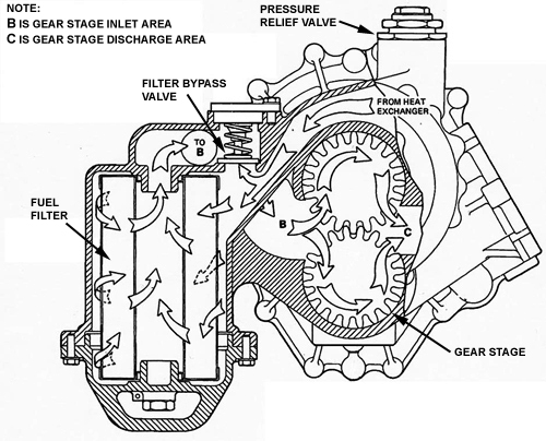
Cutaway schematic diagram of the engine driven fuel pump ARGO-TECH 708600 SERIES showing the high pressure gear stage together with the fuel filter element.
The fuel filter is equipped with a filter bypass valve (shown on the figure above) which opens at a preset differential pressure in case of a filter element blockage, to allow fuel to bypass the filter element and the engine to continue operating. When the differential pressure reach the value to open the bypass valve, a pressure switch sends a signal to the cockpit to notify crew for the situation to initiate the proper procedures for the abnormal situation.
The filtered fuel is then enters the high pressure gear stage of the pump through internal passages where the pressure rises to the nominal pressure can deliver.
The capability of the high pressure gear stage of the pump in pressure is 850 to 900 psi (pounds per square inches), and in volume displacement 50 to 60 U. S. Gallons, or 13.000 litters per hour at maximum nominal operating speed of the pump at 6250 rpm for this pump, and when the engine operates to take off power.
In any case the pump capability in volume displacement is bigger than the fuel feed needs of the engine. The excess fuel volume returns from the fuel metering unit through internal passage to the inlet of the high pressure stage (shown in the first figure) of the pump and circulates again. A pressure relief valve in installed at the exit of the high pressure stage of the pump, which opens to a preset pressure value to avoid pump damage in overpressure condition.
At the exploded view figure to the left you can see all the parts the engine driven fuel pump consists off. The two parts of the body upper left and lower down, the support bearings of the high pressure stage gears under numbers 460, 465, 425, 430, same stage gears with numbers 440, 445, the shaft connecting the two pump stages (low and high pressure) number 410, the shaft driving the fuel metering unit number 370, and finally the low pressure pump stage rotor (centrifugal type) with number 265.
Photos of the most significant parts of the pump you can see on the following pages :

