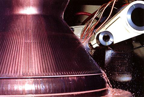
Thrust Chamber
Chemical rocket propulsion is essentially a controlled explosion of some of the most volatile elements on the periodic chart. The epicenter of the event is the rocket engine thrust chamber.
In late afternoon on December 18, 1992, a three- stage Delta II lifted a 4,150-pound NAVSTAR II global positioning system (GPS) satellite into orbit, the 17th entry of an eventual 24-satellite constellation that will enable ground-, air- or sea-based users to accurately determine their true location within 50 feet, as well as the precise time within a millionth of a second under all weather conditions. The primary engine for the three-stage Delta II launch vehicle was Rocketdyne’s RS-27A engine, which has a sea-level thrust of 201,000 pounds, and was augmented by nine solid rocket motors that are strapped to the exterior of the vehicle.
Earlier that same year-on June 9-an Atlas IIA carried a 6,000-pound INTELSAT K spacecraft into low Earth orbit that provided new telecommunications links between Europe and North and South America. Primary propulsion for the two-stage vehicle was the Atlas MA-5A engine system, developing 484,000 pounds of thrust.
And in January of 1993, the Space Shuttle roared aloft on mission STS-54 with a payload of more than 46,000 pounds, including NASA’s Tracking and Relay Satellite, which will enable high-capacity communication with the shuttle and other launch vehicles. Powering that flight were three Space Shuttle Main Engines (SSMEs), each generating 489,000 pounds of thrust.
The three missions demonstrate a wide variety of payload capacities-in weight and applications. In each situation, the engine and vehicle were closely matched to the declared need, missions that comparatively indicate the wide size spectrum of spacecraft currently being placed in Earth orbit.
Our discussion here, however, will be concerned with more basic aspects of those engines-in particular, the rocket engine thrust chamber. Understanding that portion of a liquid rocket engine is a key to an appreciation of the larger technology.
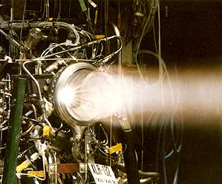
Common to all three flights was a similar fiery beginning as the main engines ignited with a resounding explosion that continued as the vehicles lifted slowly off the pads and moved upward, gaining speed with each passing moment. What actually occurred was a sustained explosion under carefully controlled conditions, a prime example of the venerable every-action-has-an-equal-and-opposite-reaction law. In each case, the law was put to work in spectacular fashion.
The precise site and the means for controlling that sustained explosion is the engine thrust chamber, the very heart of the propulsion system-and where form truly conforms to function. In the RS-27A, the Atlas MA-5A and the SSME, that form is very much predicated on mission requirements, which traditionally include thrust needs, flight duration and the number of starts the engine will have to endure. And further, the realities of thrust chamber design exert a heavy influence on the rest of the propulsion system.

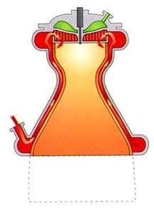
A typical, regeneratively cooled combustion chamber. Represented in red, the propellant enters the coolant liner through a manifold at the bottom of the chamber and flows upward to join additional propellant which discharges into the injector and then flows downward through the injector faceplate elements. Once inside the chamber, the propellant is mixed with liquid oxygen to initiate the combustion process. Thrust and other loads are transmitted through the structural jacket which is reinforced by vertical members.
In a liquid propellant rocket engine, the function of the thrust chamber assembly is to generate thrust by efficiently converting the propellant chemical energy into hot gas kinetic energy. That conversion is accomplished by the combustion of the propellants in the combustion chamber, followed by acceleration of the hot gas through a convergent/divergent nozzle to achieve high gas velocities and thrust.
Basic elements of the thrust chamber assembly are an injector assembly, which contains a propellant ignition device, a combustion chamber and a hot gas expansion nozzle. Depending upon the nozzle expansion ratio and size, which impacts both nozzle fabrication and handling, the expansion nozzle may be either an integral part of the combustion chamber or a separate component part that attaches to the exit end of the combustion chamber assembly.
As part of the thrust chamber assembly, the essential function of the injector assembly is to uniformly inject liquid propellants into the combustion chamber at the proper oxidizer/fuel mixture ratio. The injector introduces propellants into the combustion chamber in a manner to promote propellant mixing and droplet atomization by either impinging propellant streams, swirling, shear mixing or other mechanical means of achieving maximum atomization.
Within the combustion chamber, ignition is achieved and vaporization of the atomized droplet is initiated by heat transfer from the surrounding 6500°R hot gas. The size and velocity of the droplets change continuously during their entrainment and acceleration in the hot gas combustion flow. As the combustion process progresses, the vaporized propellants are mixed rapidly, heated and react, thereby increasing the gas phase flow rate within the combustion chamber.
Typically, a well-designed injector atomizes a large population of propellant droplets to less than 0.004 inches (100 microns) in diameter. Therefore, with proper injector and combustion chamber design, all droplet vaporization and combustion is completed before the combustion gas enters the chamber’s narrow throat area. As the combustion gas enters this convergent section of the combustion chamber, it is accelerated to sonic velocity (4,000 to 5,000 ft/sec) and then to supersonic velocity as the chamber widens. Within the divergent section of the nozzle extension, the combustion gas continues to expand with increasing velocity (10,000 to 15,000 ft/sec, two to three miles/sec, or three to four times the speed of a high-powered rifle bullet) until it is expelled at the desired nozzle area ratio and gas static pressure to maximize thrust chamber performance.
As an integral and important component of the thrust chamber assembly, the combustion chamber itself must be specifically designed to satisfy the operating requirements of that engine. The basic components of a combustion chamber, depending upon the type, are the coolant inlet and discharge manifolds, an internal coolant liner consisting of tubes or channels and an external structural assembly capable of carrying the thrust, pressure, thermal, vibration and other dynamic or flight loads. The hot gas wall contour of the internal coolant liner is aerodynamically designed to provide maximum performance and thrust for the engine operating conditions.
Combustion chamber designs are generally categorized or identified by the hot gas wall cooling method or the configuration of the coolant passages, where the coolant pressure inside may be as high as 7,000 psia. The high combustion temperatures (4500 to 6500°R) and the high heat transfer rates (up to 100 Btu/in2-sec) encountered in a combustion chamber present a formidable challenge to the designer. To meet this challenge, several chamber cooling techniques have been utilized successfully.
Regenerative cooling is the most widely used method of cooling a combustion chamber and is accomplished by flowing high-velocity coolant over the back side of the chamber hot gas wall to convectively cool the hot gas liner. The coolant with the heat input from cooling the liner is then discharged into the injector and utilized as a propellant. All of Rocketdyne’s (now Rocketdyne Propulsion and Power, a part of Boeing) large engines, with the exception of the Lance, are regeneratively cooled.
Earlier combustor (thrust chamber) designs, such as the V-2 and Redstone, had low chamber pressure, low heat flux and low coolant pressure requirements, which could be satisfied by a simplified “double wall chamber” design with regenerative and film cooling. For subsequent rocket engine applications, however, chamber pressures were increased and the cooling requirements became more difficult to satisfy. It became necessary to design new coolant configurations that were more efficient structurally and had improved heat transfer characteristics.
This led to the design of “tubular wall” combustion chambers, by far the most widely used design approach for the vast majority of large rocket engine applications. These chamber designs have been successfully used for the Thor, Jupiter, Atlas, H-1, J-2, F-1, RS-27 and several other Air Force and NASA rocket engine applications. The primary advantage of the design is its light weight and the large experience base that has accrued. But as chamber pressures and hot gas wall heat fluxes have continued to increase (< 1500 psia), still more effective methods have been needed.
One solution has been “channel wall” combustors, so named because the hot gas wall cooling is accomplished by flowing coolant through rectangular channels, which are machined or formed into a hot gas liner fabricated from a high-conductivity material, such as copper or a copper alloy. A prime example of a channel wall combustion chamber is the SSME, which operates at 3,000 psia nominal chamber pressure at 6500°R for a duration of 520 seconds. Heat transfer and structural characteristics are excellent.
In addition to the regeneratively cooled designs mentioned above, other combustion chamber designs have been fabricated for rocket engines using dump cooling, film cooling, transpiration cooling, ablative liners and radiation cooling. Although regeneratively cooled combustion chambers have proven to be the best approach for cooling large liquid rocket engines, other methods of cooling have also been successfully used for cooling thrust chamber assemblies. Examples include:
Dump cooling, which is similar to regenerative cooling because the coolant flows through small passages over the back side of the combustion chamber wall. The difference, however, is that after cooling the combustion chamber, the coolant is discharged overboard through openings at the aft end of the divergent nozzle. This method has limited application because of the performance loss resulting from dumping the coolant overboard. To date, dump cooling has not been used in an actual application, but it might be of value in a convectively cooled space probe engine that operates with a very high wall temperature and uses hydrogen as the propellant and coolant.
Film cooling provides protection from excessive heat by introducing a thin film of coolant or propellant through orifices around the injector periphery or through manifolded orifices in the chamber wall near the injector or chamber throat region. This method is typically used in high heat flux regions and in combination with regenerative cooling. The F-1, J-2, Atlas, RS-27 and SSME have all used this technique.
Transpiration cooling provides coolant (either gaseous or liquid propellant) through a porous chamber wall at a rate sufficient to maintain the chamber hot gas wall to the desired temperature. The technique is really a special case of film cooling and has been used on the injector faces of the J-2 and the RS-44, as well the SSME.
Cooling channels are cut into the reverse side of an SSME main combustion chamber.
During operation, coolant flows through these channels to cool the inner liner which contains hot gas at combustion temperatures that can reach 6500°R.
With ablative cooling, combustion gas-side wall material is sacrificed by melting, vaporization and chemical changes to dissipate heat. As a result, relatively cool gases flow over the wall surface, thus lowering the boundary-layer temperature and assisting the cooling process. Rocketdyne’s Lance missile engine and the Peacekeeper fourth-stage engine both employ ablative cooling.
And finally, with radiation cooling, heat is radiated from the outer surface of the combustion chamber or nozzle extension wall. Radiation cooling is typically used for small thrust chambers with a high-temperature wall material (refractory) and in low-heat flux regions, such as a nozzle extension. The RS-21 Mariner/Viking Orbiter spacecraft was an early example of this technology.
Selection of the optimum cooling method for a combustion chamber depends on many considerations:
Propellants.The properties of the combustion products have a significant effect on the heat transfer rates on the hot gas side and the properties of the coolant have a significant effect on the coolant side film coefficient. Both of these factors affect the selection of the coolant method.
Chamber pressure.As the chamber pressure increases, the only cooling methods that can satisfy the requirements are regenerative cooling only or regenerative cooling combined with film cooling.
Available coolant pressure. For a regenerative cooling system, the coolant supply pressure must be sufficient to flow the coolant through the narrow cooling passages at high velocities. Cooling capability is directly related to the available pressure drop. In the absence of high supply pressure, other cooling techniques must be used.
Combustion chamber configuration. The configuration of the combustion chamber affects the hot gas film coefficient profile along the length of the chamber, which, in turn, influences the cooling method.
Combustion chamber material. Depending on the cooling technique, it is important that the materials selected for the design have the correct properties for that coolant method. For regenerative cooling, it is important that the material have high strength at elevated temperatures and, also, have a high thermal conductivity. For film-cooled chambers, a material with high strength at elevated temperatures is desirable, while for radiation-cooled chambers, a material that has a high melting temperature, such as a refractory, is desirable. An ablative cooling design depends on non-metallic materials developed specifically for that application.
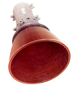
The engine from the Peacekeeper Stage IV serves as an example of ablative cooling. The orange-red lining in the thrust chamber cools by burning away during operation.
The primary influence on delivered engine performance is the combustion chamber combustion process, which is largely dictated by two parameters: (1) the propellant mixing/distribution efficiency and (2) the evaporation/reaction efficiency. To establish and maximize the combustion or energy release efficiency, computer programs have been developed that predict efficiency, based upon the injector/combustor configuration, propellants, propellant state (liquid or gas) and the operating conditions.
Using these variables, an analytical model of the injection process outputs the spatially distributed gas atomization (heat and mass transport processes, as well as physical property changes) for an injector element. An analytical model of the combustion process is then used to calculate the axisymmetric two-dimensional mixture ratio distribution and mixing, and the propellant evaporation losses. The output of this analysis provides an energy release efficiency that permits optimization of the injector and combustor designs. The overall combustion chamber performance is the sum of the combustion performance and the other inefficiencies that occur within the thrust chamber.

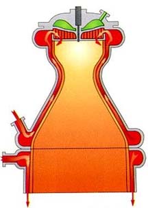

Four variations of thrust chamber cooling are illustrated. From left to right: regenerative cooling as employed in a typical thrust chamber configuration; regenerative cooling augmented by radiation cooling of a nozzle extension; regenerative cooling augmented by dump cooling from passages in the nozzle extension; and regenerative cooling augmented by film cooling along the inside wall of a nozzle extension
Combustion stability is important to an engine from both an engine performance and hardware integrity standpoint. Increased stability is often obtained by changing operating points that decrease combustion efficiency. Hence, it is necessary to consider performance and combustion stability together for optimization of a thrust chamber assembly. Evaluation of a thrust chamber assembly for combustion stability includes analyses for nonacoustic, hybrid and acoustic modes of instability. Computer programs have been developed that are used to analyze all three types of combustion instability and to predict the effects of changes in the feed system, injector and combustion chamber configuration. Nonacoustic modes of combustion instability are propellant feed system, coupled chugging and buzzing modes, which are subacoustic in frequency.
The earliest major contributions to developing an understanding of the mechanism of rocket engine combustion instability and potential solutions were contributed by the F-1 Project First group, which was formed at Rocketdyne in 1962. As a result of the analysis by the Project First group and an extensive hot-fire test program on the F-1 engine, it was demonstrated that the addition of baffles was very effective for eliminating acoustic combustion instability. As a result of the demonstrated effectiveness of baffles on the F-1 program, baffles have been used on many subsequent injector designs where acoustic combustion instability was either a concern or a reality.
Acoustic stability aids include baffles attached to the injector and acoustic cavities, which are stability damping devices located in the combustion chamber hot gas wall that employ tuned lengths or other open areas exposed to the combustion process. They are most effective when located at the intersection of the injector outer diameter and the combustor wall. A prime example of the use of this stability aid is the SSME main combustion chamber. The usual configurations of acoustic cavities are as Helmholtz resonators, or quarter-wave slots.
Typically, the internal environment of the cavity is controlled by bleeding a small amount of the coolant into the cavity to permit accurate analysis of its acoustic characteristics. Adding acoustic cavities to a combustion chamber usually results in a significant impact on the chamber design. With acoustic cavities, structural and cooling requirements are more difficult to satisfy and cooling of the entrance to the cavities may be difficult.
The most important parameters involved in the design of the hot gas wall on a regeneratively cooled chamber are the thermal conductivity of the material, the strength of the material at elevated temperatures, the material maximum operating temperature and the coolant passage dimensions. A high thermal conductivity material for the chamber liner or tubes is desirable, since it minimizes the wall temperature for a given heat flux. If the material also has high strength at elevated temperatures, the wall thickness can be reduced, which, in turn, further reduces the wall temperature. Evaluation of potential coolant passage configurations must also consider fabrication capabilities that limit the range of coolant passage dimensions that can be successfully fabricated. In the design of both tubular and channel wall chambers, the number of coolant passages and their configuration is an iterative procedure of heat transfer, structure, pressure loss, fabrication feasibility and the numb er of passages that can fit into the chamber geometry.
Tubular chambers are constructed by brazing together an assembly consisting of the coolant tube stack, which forms the internal contour of the chamber, the coolant manifolds at the aft and forward ends of the coolant tube stack, and either an outer partial shell that contains the coolant tube stack or a group of circumferential bands uniformly spaced along the length of the tube stack to provide hoop strength for carrying internal pressure loads. For tubular designs with bands uniformly spaced along the length, the tube cross section is required to transmit not only the thrust loads but also the transverse loads between each band. Typically, the tube stack is fabricated from nickel, a high-strength nickel-base alloy or a stainless steel. The manifolds, shell and/or bands are typically fabricated from a high-strength nickel-based alloy. If hydrogen is the coolant, either a material must be selected that is not subject to hydrogen embrittlement or special features must be include d in the design to avoid contact of the hydrogen and the embrittling material.
Channel wall chambers are typically fabricated by machining or forming the channels in a copper or copper alloy liner. The channels in the liner are then “closed out” either by electrodepositing nickel or copper over the channel or by brazing or liquid interface diffusion bonding (LIDB) the liner inside a close-out structure. The coolant liner is inserted into a structural jacket fabricated from a high-strength material that transmits the chamber thrust and transverse loads. The jacket typically contains coolant manifolds at the forward and aft ends of the chamber, and, therefore, it is necessary to attach the coolant liner to the structural jacket at those locations. The coolant liner, however, may or may not be attached to the structural jacket at other locations.
Building on those basics, more cost-effective launch systems and rocket engine designs will and must be developed if the United States is to remain the world’s leader in space. Accordingly, studies continue on methods to improve thrust chamber designs.
Major areas of investigation include improved material properties, fabrication methods and analysis techniques. Experimental materials programs are in progress to improve the strength of high-conductivity materials for the coolant liner or tubes. Other programs are in progress to investigate vacuum plasma spray deposition, automatic machine weld deposition, stereo lithography, high-temperature coatings, casting, laser and waterjet machining and other advanced automated machining techniques.But even with improvements in the new generations of rocket engines sure to arrive in the next century, the emphasis will still be on getting the biggest bang for the buck in robust systems that will carry more for less. And then, as now, the heart of the system will remain the thrust chamber.
Note: This article is a reproduction of the Boeing Engineering at http://www.engineeringatboeing.com/, written by Joseph Duesberg.