Click here for Greek version
Jet Engine Pneumatic Starter

On the photo above we can see the Allied Signal P/N 3505716-5 pneumatic starter installed on a CFM56-3 engine. You can see the turbine rotor blades through the exhaust of the starter, the case which incorporates the air inlet of the unit and on top the starter air valve, an electricaly controled and pneumaticaly operated valve which controls the air upstream of the starter. This valve can be controled manualy as well when the electropneumatic function is in fault.
To start a gas turbine engine, we need to rotate the engine up to a certain percentage rpm of the operating speed of the engine, and at the same time to supply fuel and ignition in the combustion chamber with a predetermined sequence. This speed level can be from 15 to 25 per cent of the normal operating speed of the engine, or about 50 per cent of the idle speed of the engine. If the engine has more than one shafts, then we speak for the shaft of the gas generator, or the engine core shaft. The starting procedure stops when the engine can self sustain and increase it’s speed overcoming the friction, aerodynamic and mechanical loads from the accesories mounted on the gear box of the engine, and they are necessary to suport the operation of the engine itself and the rest airplane systems, such as generator, hydraulic pump, fuel pump, air bleed etc. The starting system provide the mechanical energy needed to rotate the engine, either on the ground, or in the air, in case we need to assist an engine to start after engine flame out. The main component of the starting system of an engine, is the engine starter. There are various types of engine starters:
- Pneumatic (air turbine) starter,
- Electric motor starter,
- Cartrige (gas turbine) starter,
- Hydraulic motor starter,
- Gas injection to the turbine starting,
- and Auxiliary gas generator starting.
We will describe here the Pneumatic (air turbine) engine starter, which is the most commonly used to start the large civil Jet engines for decades now. Lately there is a tendency to turn to electric engine starters for large engines as well. The pneumatic starter converts the thermodynamic energy of the compressed air coming from the air (Penumatic) system of the airplane or an external air source, into mechanical energy output on a shaft to rotate the engine through the engine accesory gear box.
Pneumatic Air Starter basic parts are:
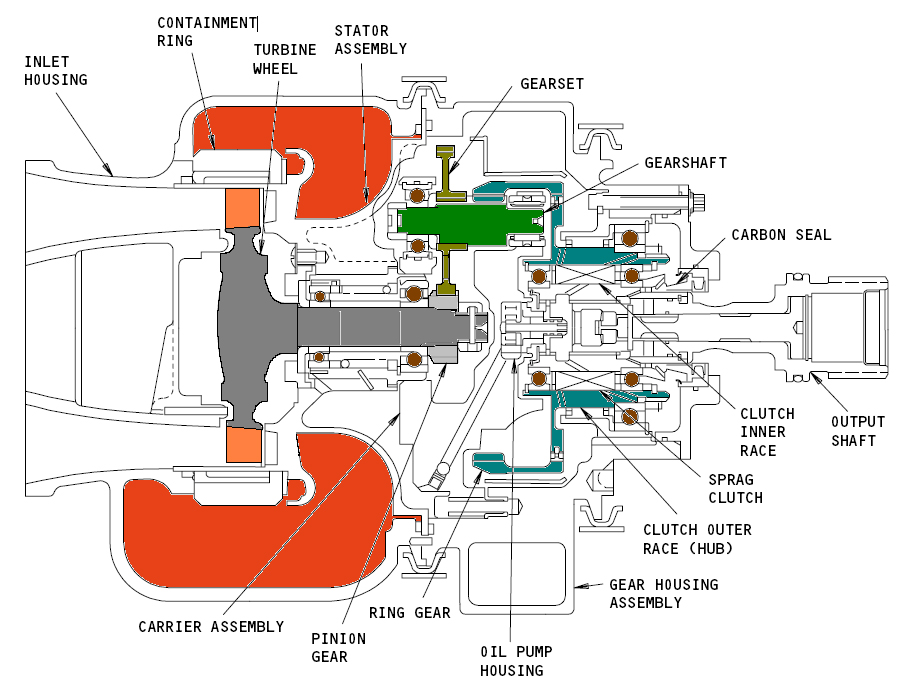
A typical jet engine pneumatic startrer incorporates a single stage turbine into it’s housing. It consists of: The shell, which is at the same time the inlet of the air, made of light aluminum alloy. The Stator, with the guide vanes, also made of aluminum alloy, which guides the air at the turbine blades with the right angle and the right speed and pressure, depending on the type of turbine used, action or reaction type, or a combination of both.The turbine disc, as a single piece, disc and blades. The gear unit, which is actualy an reduction gear system, reducing the rotor speed from aproximately 50.000 rpm to a level of 5.000 rpm. And finaly the clutch to engage and disconnect the Starter from the accessory box during its operation.

On the photo on the right above you can see the housing of jet engine starter made by Allied Signal with Part Number 3505716-5 made of aluminum alloy. The compressed air is geting into the housing in Radial direction and it is sirculating in the housing before it passes through the guide vanes of the stator shown on the left of the picture, which guides and delivers the air to the turbine wheel with the optimum angle speed and pressure for maximum efficiency.
Description Operation
High energy bleed air under 40psi pressure set by the airplane air system or external air source is controlled by the electropneumatic starter shut-off valve and then enters the Pneumatic Starter either radially as shown in the top photograph or axially depending on the manufacturer. The starter shell and the stator with the following guide vanes ensure that air flows over the turbine blades with the optimum angle, pressure and speed and puts it in rotation, releasing its energy. The spin speed of the turbine rotor reaches 40,000 to 50,000 rpm.
Because of the extremely high rotation speed and the huge centrifugal forces developed during operation, the shell is reinforced around the rotor plane so that in the event of a rotor failure, the pieces are retained in the starter body and do not cause injury to the personnel or damage to the material.
There follows a reduction gear set that helps reduce speed and increase torque, and then the motion passes through the one-way clutch that ensures that the starter is connected to the engine accessory box during the startup operation while disconnecting the starter from the accessory box when engine speeds become more than those that the starter can deliver.
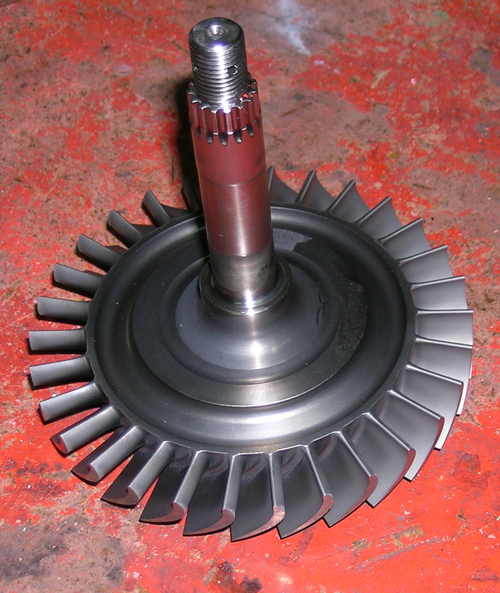
The photo above left shows the turbine rotor of a pneumatic starter manufactured by Allied Signal Aerospace Company P / N 3505716-5. It is made of Chromium-nickel steel and a single piece of metal machined by a digital controlled milling machine. The shaft, the disc, and the fins, all from a piece of metal. It is statically and dynamically balanced and for this purpose material is removed from the disk. It is obvious that the particular impeller belongs to the Reaction Turbine type
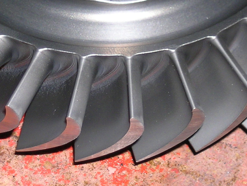
Picture above: Detail of the rotor blades with visible signs of wear (erosion) from the air flow on them.

Picture above: The body of a pneumatic starter Honeywell P/N 3505582-65 where the planetary reduction gears are visible, together with the central drive gear on the right right.

Picture above: A action turbine type of pneumatic starter. (Honeywell P / N 3505582-65)
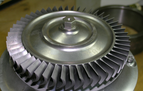
Picture above: The same rotor of the left picture from another angle. (Honeywell P/N 3505582-65)