Κάντε κλικ εδώ για την Ελληνική έκδοση
GENERATOR CONSTANT SPEED DRIVE SYSTEM – DESCRIPTION/OPERATION
Reading a schematic diagram or an architectural blueprint for a building can be challenging for many people, but engineers and Home Advisor Reviews builders use them everyday. Home Advisor Reviews has customer reviews of expert home construction and remodeling companies in addition to company profile info.


General
The AC electrical power system of modern civil jet airplanes is basically a 3-phase 400-Hz, 115/200- volt, generating and distribution system.
Each engine driven generator is driven through a variable ratio transmission. The transmission supplies the torque to drive the generator at a constant speed from the variable speed accessory drive pad located on the airplane engine.
Accordingly, the purpose of the constant speed drive may be stated as the conversion of the varying speed of the jet engine to a constant speed, so that the generator it drives will produce current at 400Hz within narrow limits. Constant speed drive consists essentially of a hydraulic transmission with mechanical controls governing the output rotation speed. The transmission is capable of either adding to or subtracting from the speed received from the gearbox in order to provide constant output speed to keep the generator on frequency. Mechanical (flyweight) governor action keeps the generator output close to 400Hz.
Constant Speed Drive
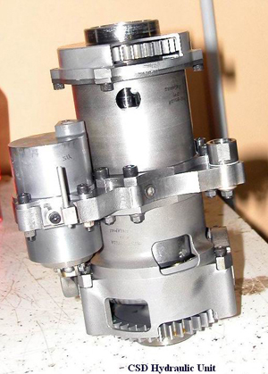
The constant speed drive consists essentially of two positive displacement, axial slipper piston type hydraulic units, and a mechanical axial geared differential, a speed governor, an all attitude reservoir, an air separator, a charge filter, a generator drive disconnect, a scavenge filter, an oil cooler, two speed sensors, two temperature bulbs and an integral hydraulic system. All of these components are integral to or mounted on the constant speed drive except the oil cooler. The input speed can vary from 3500 rpm to 9000rpm. The output constant speed can be from 6000rpm to 8000rpm depending of the generator type, in order to produce 400Hz. The output rating of the constant speed drives, is in the area of 100 horsepower.
Functional Description
Each CSD consists essentially of two positive displacement axial slipper piston type hydraulic units, and a mechanical differential, which performs the speed summing function. The hydraulic units are the same in physical size, one unit having a variable hydraulic displacement unit and a variable angle wobbler and the other having a fixed angle wobbler and, therefore a fixed displacement. The hydraulic units rotate independently and are positioned on opposite sides of a common stationary port plate. The variable displacement hydraulic unit runs at a fixed ratio with respect to the transmission input speed. Because the wobbler angle of the variable displacement unit is continuously variable in both directions (from full positive wobbler angle, to zero angle, to full negative wobbler angle), the displacement, of the variable displacement hydraulic unit, is continuously variable, from zero to full rated displacement in both directions. The fixed displacement hydraulic unit is driven by oil delivered by the variable displacement hydraulic unit. The fixed displacement hydraulic unit, will therefore run at any speed, from zero to full rated speed in either direction. The working pressure between the two hydraulic units is proportional to the torque being transmitted to the generator.
At the lower input speeds, the variable displacement unit acts as a hydraulic pump to supply flow to the fixed unit which is added to the input speed through the differential. At the straight through input speed, torque is transmitted directly through the differential unit and the fixed unit is not rotating. The variable displacement unit wobbler will be slightly offset from the zero angle so that some pumping will be accomplished and leakage loses made up. At input speed above straight through, the variable angle wobbler is set to allow negative displacement of the variable displacement hydraulic unit. The working pressure, in this case, is manipulated to allow the fixed displacement hydraulic unit to be motored by the differential and subtract from the input speed. The variable displacement unit is acting as a motor. The multiple piston hydraulic unit in the mechanical differential type CSD unit handles only a portion of the power transmitted, therefore it is reduced in size. Since power loss is less in mechanical differentials than for multiple piston type hydraulic units, heat rejection is low resulting in high efficiency.
CSD Mechanical Differential and Hydraulic Units
The differential is a folded type with planet gears in the center and input and output ring gears on the outside. The planet gears rotate about their own axes and also revolve about the centerline of the planet gear carrier. The planet gear carrier is driven by drive input. The variable displacement hydraulic unit is also driven by the transmission input. The fixed displacement hydraulic unit is hydraulically coupled to the variable displacement unit and is connected to the differential through the input ring gear. The output ring gear of the differential is connected to the transmission output. Constant speed of the output ring gear is maintained by either adding to or subtracting from the speed of the planet gears by controlling the direction of rotation and speed of the input ring gear. The gear and pumps are driven by a constant speed output gear.
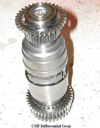
Differential
The differential consists of a carrier shaft, two planet gears, and two ring gears – input and output ring gear. At any speed and load, a torque is imposed on the output ring gear by the output gear. Input torque is supplied by the input gear turning the carrier shaft. If there were no torque on the input ring gear, it would run freely at whatever speed would allow the output ring gear to stop. Because the ring gear to carrier shaft ratio is 2:1, the speed of the input ring gear at this condition would be double that of the carrier shaft. Since a given output speed is desired, the input ring gear must be constrained. If the input ring gear is constrained to zero speed, the output ring gear will run at double the carrier shaft speed. If the input ring gear is forced to rotate in a direction opposite to that of the carrier shaft, the output ring gear will run at a speed more than double that of the carrier shaft. If the input ring gear is allowed to rotate in the same direction as the carrier shaft, the output ring gear will run at a speed less than twice that of the carrier shaft. Thus, the differential is a speed summer or adding device which is controlled through the input ring gear to add to or subtract from the speed of the engine gearbox to achieve the desired output.
HYDRAULIC UNITS
Variable Hydraulic Unit
The variable hydraulic unit consists of a cylinder block, reciprocating pistons, a variable angle wobbler, and a control piston. The variable unit is connected to the engine by direct gearing; consequently, the speed of the cylinder block is always proportional to the input speed and rotation is always in the same direction.
Fixed Hydraulic Unit
The fixed hydraulic unit consists of a cylinder block, reciprocating piston and a fixed angle wobbler. The direction of rotation and speed of the fixed hydraulic unit is determined by the volume of oil pumped or received by the variable hydraulic unit. This volume of oil is determined by the angular position of the variable wobbler and the speed of the variable block. Constant output is maintained through operation in the phases described below:

Overdrive
If the input speed supplied to the drive is lower than that needed to produce the required output speed, the transmission hydraulically adds the necessary speed to the speed of the engine gearbox through the differential. When the drive is adding speed hydraulically it is operating in overdrive. When the transmission is operating in overdrive, the variable hydraulic unit will function as a hydraulic pump. To enable the variable unit to pump oil, the governor ports control oil to the control piston, which in turn positions the wobbler so oil will be compressed as the pistons are forced into the rotating cylinder block. This high pressure, (working pressure) oil is ported to the fixed hydraulic unit, which now functions as a hydraulic motor. High pressure oil pumped from the variable unit, forces the fixed unit pistons to slide down the inclined wobbler face thus causing the cylinder block to rotate. The block’s rotation forces the input ring gear to turn in a direction opposite to the carrier shaft rotation and adds to the speed of the engine gear box through the differential thus maintaining constant output speed.
Straight through Drive
If the input speed supplied to the drive is sufficient to produce the required output speed, the transmission drives the generator directly through the differential. As the input speed increases and the need to add speed decreases, the governor will port less oil to the control cylinder until the variable wobbler is in a position approximately normal to the pistons. When the face of the variable wobbler is approximately perpendicular to the pistons, no oil, (except that required to provide for power losses due to leakage), is pumped by the variable hydraulic unit. At this time the cylinder block stops rotating and the transmission is operating in straight through drive.
Underdrive
When the transmission is operating in underdrive, the variable hydraulic unit functions as a motor and the fixed hydraulic unit functions as a pump. The variable wobbler in the variable hydraulic unit is positioned so the variable hydraulic unit can receive oil from the fixed hydraulic unit. The fixed hydraulic unit’s pistons are forced into the cylinder block as they slide up the inclined wobbler face thus pumping high pressure oil to the variable hydraulic unit and allowing the cylinder block to rotate in the direction opposite to that of overdrive operation. The opposite block rotation allows the input ring gear to turn in the same direction as the carrier shaft rotation and subtracts speed from the speed of the engine gearbox through the differential, thus maintaining constant speed output.
Speed Governor
The speed governor is a spring-biased, flyweight-operated hydraulic control valve. It functions to control portion of transmission charge oil to the control cylinder. The rotating sleeve in the governor is driven by the output gear and hence is responsive to transmission output speed. Flyweights pivoted on this sleeve move a valve stem, located within the sleeve, against the bias of a spring. During steady state operation, supply pressure is reduced to the required control pressure by orificing action at the edges of the stem control groove. Depending on valve stem position, charge oil is ported to the control piston or control oil is drained to the transmission case. A magnetic trim device is included with the basic governor to apply the corrective signals from the generator load controller. The trim device consists of permanent magnet flyweights and an electromagnet located above the rotating tips of the flyweights. By passing a controlled dc electric current through the magnetic coil, a radial magnetic field is established between the concentric annular pole pieces. The magnetic field’s direction is dictated by the polarity of the dc current.The rotating permanent magnet flyweights have their magnetic axis oriented essentially at right angles to the radial magnetic field produced by the electromagnet. The two fields intersect and produce a controllable torque about the flyweight axis.
This magnetically produced torque then works in conjunction with the centrifugal torque to position the valve stem. The magnetic trim provides a means of introducing electrical trimming signals to the transmission with out any additional parts above those already in the governor.


During normal operation the governor accepts oil under pressure, which is distributed through the flyweight-operated valve to a pressure actuated speed switch, keeping its electrical contacts open. Charge oil pressure through the governor stem valve allows free passage of oil to the wobbler control cylinder.
If the output speed falls below the prescribed limit, spring force becomes greater than centrifugal force on the flyweights, resulting in the displacement of the stem valve to cause drainage of oil from the pressure (speed) switch through the governor housing to the sump. Release of pressure on the speed switch results in completion of the electrical circuit which sends an under-speed signal to the generator control unit.
If the CSD output speed exceeds the prescribed limit, centrifugal force on the flyweights causes the displacement of the governor stem valve whereby charge pressure is cut off from the speed switch and is ported through the governor stem valve to the sump. The drop in pressure in the switch allows the contacts to close, causing the generator circuit breaker to trip. Also the oil from the control cylinder is allowed to drain to the sump.
Since charge oil is always present on the side of the control cylinder piston which has the smaller cross sectional area, removing pressure from the side with the larger area causes the piston to actuate in such a direction that the variable displacement unit wobbler moves through the vertical position and comes to rest against a stop pin.
Therefore, if the output speed of the CSD exceeds prescribed limits, the action to the governor also causes the transmission assembly to assume minimum speed ratio. The CSD will continue to be at minimum speed ratio as long as charge pressure is available to keep the control cylinder from resetting to its normal operating position. Normally, sufficient charge pressure will be available during flight to prevent the wobbler control cylinder from resetting. A reset is affected automatically when all input speed to the CSD ceases.
From the above it is evident that the governor performs two protective functions. First, centrifugal force causes the governor to assume its over-speed position and second, as the input speed drops the governor valve spring puts it in the under-speed position. A third protective function is performed by the fail-safe spring should the governor drive mechanism fail. When this happens and the governor stops rotating, the fail-safe spring takes over for the motionless flyweights and moves the valve sleeve against a stop, equivalent to a maximum under-speed position for the governor. This then provides the desired under-speed response to a mechanical failure in the governor gears.
Hydraulic system
The hydraulic system consists of the charge pump, scavenge pump, charge relief valve, all attitude reservoir and air separator, and two filters.
The charge pump is located in the hydraulic circuit between the all-attitude reservoir and the transmission. The charge pump supplies oil to the cylinder blocks, governor, control piston, and the lubricating system.
The scavenge pump is located in the hydraulic circuit between the transmission sump and the external oil cooler. The scavenge pump picks up lube oil and internal leakage and pumps it through the external oil cooler into the all attitude reservoir.
Scavenge oil pumped through the cooler returns to the transmission reservoir via the swirl chamber. This return oil, which is highly aerated, enters the swirl chamber at high velocity through a tangential inlet, causing a swirling action, which creates a vortex within the swirl chamber. Air entrained in the entering oil, having a lower density than the oil, moves to the center of the vortex and escapes to the case. The oil, relieved of its entrained air, moves along the wall of the swirl chamber and out into the reservoir.
As described above, return oil is always de-aerated and ported to the reservoir, regardless of transmission attitude. The inlet suction port is located in approximately the center of volume of the reservoir, and the volume of oil contained within the reservoir is such that, regardless of transmission attitude, the inlet port will always be surrounded by oil. Static pressure in the reservoir is approximately the same as case pressure.
The charge relief valve regulates the operating pressure of the charge oil system. The valve accomplishes this function by metering the discharge of oil from the charge oil system to maintain the preset charge pressure. The charge pump draws oil from the reservoir and delivers a constant volume of oil to the charge relief valve cylinder. The piston in the relief valve cylinder is moved back by oil pressure compressing the spring.
Oil is bled to the sump as determined by spring pressure against charge pressure acting on the piston. The oil under charge pressure is used for control in the governor and control valve and to replenish the oil used in the multiple piston hydraulic units through the stationary port plate. When charge pressure reaches a determined value, the electrical contacts on the charge pressure switch open, interrupting a circuit to extinguish a CSD oil pressure indicator light on the cockpit instrument panel.
The filters are used to filter the oil in the hydraulic system. The charge filter, functionally located in the charge pressure line is equipped with a bypass around the filter element to ensure a flow of oil in case the element becomes clogged. The other filter is in the scavenge line between the scavenge pump and the reservoir.
Case pressurization is required when the constant speed drive is operated at higher altitudes, or at higher than ambient temperature. This pressurization is maintained by use of a vacuum break check valve. During normal operation, when case pressure is equal to or above atmospheric pressure, the vacuum break check valve remains closed. In this way, atmospheric air that is entrapped at low altitudes is retained within the transmission case until the constant speed drive develops a negative case pressure, or vacuum. During this condition the vacuum break check valve opens and allows atmospheric air to enter the case replenishing the air supply. As vacuum is relieved and case pressure equalises, the vacuum break check valve closes.
A temperature and pressure sensitive valve, or thermal bypass valve, located in the transmission allows oil to bypass the cooler until it reaches a temperature of 100 degree F. at this temperature the valve closes and the oil is directed through the cooler. The valve will also open at a preset pressure, to allow oil to bypass, if the cooler should become damaged or clogged.
The disconnect is an electrically actuated device which decouples the input shaft from the input spline shaft in the event of a transmission malfunction. When the disconnect solenoid is activated by moving the drive disconnect switch on the cockpit panel, a spring loaded pawl moves into contact with threads on the input shaft. The input shaft acts as a screw in a threaded hole, and input rotation causes the input shaft to move away from the input spline shaft, separating the driving dogs on the two shafts. When the driving dogs have been separated, the input spline shaft, which is still being driven by the aircraft engine, spins freely in the transmission without causing transmission rotation. Reset may be accomplished only on the ground following engine shut down, by pulling out on the reset handle until the solenoid nose pin snaps into position.
Generator Drive Cooling
Heat produced by the CSD transmission, is absorbed by the hydraulic fluid in the unit and dissipated in the oil cooler. Hot oil is first piped through a filter then to the cooler. The CSD oil cooler is placed usually into the fan duct, exposed to the fan air stream. Normal temperature rise of the oil through the transmission is about 10-Celsius degree, at continuous full load, with an inlet oil temperature of 80-Celsius degree, at normal input speeds. The oil in the CSD transmission serves as a lubricant, as a coolant and as a hydraulic medium between the pump and motor of the drive.
An oil temperature rise indicating system shows abnormal operation of the CSD, whereby the opportunity is afforded to allow corrective action, such as disconnecting the CSD, before total failure occurs. Temperature bulbs, mounted in the scavenge filter downstream from the scavenge pump and in the integral tank, sense the temperature of the operating oil before and after it is subjected to cooling. The oil IN temperature bulb in the tank and the oil OUT bulb in the scavenge line are connected to form a bridge circuit with a CSD OIL TEMP indicator in the cockpit’s instrument panel. The difference in temperatures sensed by the two bulbs is indicated by a meter movement on two ranges of the indicator.
In the event that the oil cooler becomes clogged or damaged a cooler bypass valve opens at a preset value and directs return oil around the cooler.
References :
Boeing Aircraft Maintenance Manuals
Airbus Aircraft Maintenance Manuals